
categories: physics, automation & robotics, electronics
Hello everyone, last post in this mini-series. Two topics that come up constantly once you're actually building things instead of just calculating them on paper: driving a relay/motor/coil from a microcontroller pin with a transistor, and figuring out whether that same motor is going to cook itself if you run it continuously.
Part 1 — Sizing a transistor switch (with a flyback diode)
Think of a transistor as an electrically-controlled valve: a small trickle of current on the base ($$I_B$$) opens a much larger flow on the collector ($$I_C$$). The goal when designing the switch is to pick a base resistor $$R_B$$ that drives the transistor fully into saturation — i.e. fully "open" — so it behaves like a clean, reliable switch instead of sitting half-open and wasting power as heat.
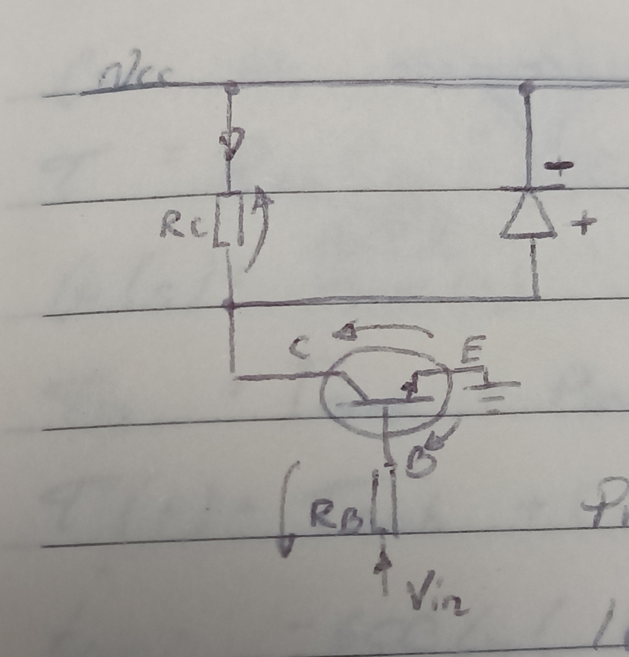
Setup: a relay coil ($$R_C = 120\ \Omega$$) is powered from $$V_{CC}=12\ \text{V}$$, switched by an NPN transistor ($$\beta=100$$, $$V_{BE}=0.7\ \text{V}$$, $$V_{CE(sat)}=0.2\ \text{V}$$), driven by a microcontroller pin at $$V_{in}=5\ \text{V}$$. A diode is wired in parallel with the coil, anode toward the collector, cathode toward $$V_{CC}$$ — this is the flyback diode, and skipping it is the single most common way people fry a transistor: a coil resists sudden changes in current, so the instant you switch it off, it tries to keep the current flowing and generates a large reverse voltage spike. The diode gives that spike a safe path to circulate in instead of blowing through your transistor.
Step 1 — saturation collector current (transistor acts as a near-ideal closed switch with a small residual drop): $$I_{C(sat)} = \frac{V_{CC}-V_{CE(sat)}}{R_C} = \frac{12-0.2}{120} \approx 98.3\ \text{mA}$$
Step 2 — minimum base current needed to sustain that collector current, from the transistor's current-gain relationship $$I_C = \beta \cdot I_B$$: $$I_{B(min)} = \frac{I_{C(sat)}}{\beta} = \frac{98.3\ \text{mA}}{100} \approx 0.983\ \text{mA}$$
Step 3 — design with overdrive. Never design right at the minimum — double it, so the transistor stays in deep saturation even as $$\beta$$ drifts with temperature or between individual parts: $$I_B = 2 \cdot I_{B(min)} = 1.966\ \text{mA}$$
Step 4 — base resistor. The base-emitter junction behaves like a diode with a ~0.7 V drop, so: $$R_B = \frac{V_{in}-V_{BE}}{I_B} = \frac{5-0.7}{1.966\ \text{mA}} \approx 2.2\ \text{k}\Omega$$ Without $$R_B$$, connecting 5 V straight to the base would short through that junction and take your microcontroller pin down with it — this resistor is what limits that current to a pin-safe couple of milliamps.
Part 2 — Will it overheat? A first-order thermal RC model
This is the same math as an RC charging circuit, just relabeled: heat losses in the windings ($$P_{loss}$$) play the role of a current source, the motor's thermal mass ($$C_{th}$$) plays the role of a capacitor storing charge, and the casing's thermal resistance to the surrounding air ($$R_{th}$$) plays the role of a resistor limiting how fast that "charge" (heat) can leak out. Voltage in this analogy is temperature.
It comes directly from the 1st law of thermodynamics — energy in must equal energy stored plus energy that leaves: $$P_{loss} = \underbrace{C_{th}\frac{dT(t)}{dt}}_{\text{stored}} + \underbrace{\frac{T(t)-T_{amb}}{R_{th}}}_{\text{dissipated (Newton's cooling law)}}$$
Data: $$P_{loss}=15\ \text{W}$$, $$R_{th}=3\ \text{K/W}$$, $$C_{th}=200\ \text{J/K}$$, $$T_{amb}=25^\circ\text{C}$$, warning threshold $$T_{target}=60^\circ\text{C}$$.
Steady-state temperature. After a long time, the motor stops heating up ($$dT/dt = 0$$), so all the generated heat has to escape through $$R_{th}$$: $$T_{ss} = T_{amb} + P_{loss}\cdot R_{th} = 25 + 15\cdot 3 = 70^\circ\text{C}$$
Thermal time constant — how "sluggish" the motor is thermally, exactly like an RC product sets how fast a capacitor charges: $$\tau = R_{th}\cdot C_{th} = 3 \cdot 200 = 600\ \text{s} \ (10\ \text{minutes})$$
Full heating curve, solving the differential equation above with $$T(0)=T_{amb}$$: $$T(t) = T_{amb} + (T_{ss}-T_{amb})\left(1-e^{-t/\tau}\right) = 25 + 45\left(1-e^{-t/600}\right)$$ Early on the motor is cold, so almost all the power goes into heating it up fast; the hotter it gets, the more power leaks out through $$R_{th}$$ and the slower the temperature rise becomes — that's exactly what the $$e^{-t/\tau}$$ term captures.
Time to hit the 60°C warning threshold — this is the number you actually want for deciding how long you can run without a fan: $$60 = 25+45\left(1-e^{-t/600}\right) \implies t = -600\ln\!\left(\frac{2}{9}\right) \approx 902\ \text{s} \approx 15\ \text{min}$$
Bonus: the same result via Laplace, since it generalizes to any input
Write the switch-on of the heater as a step: $$P_{loss}(t) = P_{loss}\cdot \mathbb{1}(t)$$, whose Laplace transform is $$\mathcal{L}\{\mathbb{1}(t)\} = 1/s$$. Transforming the differential equation (zero initial condition, $$\Delta T = T - T_{amb}$$): $$\frac{P_{loss}}{s} = C_{th}\cdot s\cdot \Delta T(s) + \frac{\Delta T(s)}{R_{th}} \implies \Delta T(s) = \frac{\Delta T_{ss}}{s(\tau s + 1)}$$ Partial-fraction it into two standard table entries and invert term by term: $$\Delta T(s) = \Delta T_{ss}\left(\frac{1}{s} - \frac{1}{s+1/\tau}\right) \xrightarrow{\mathcal{L}^{-1}} \Delta T(t) = \Delta T_{ss}\left(1-e^{-t/\tau}\right)$$ same answer as before, but this route works even if $$P_{loss}$$ isn't a clean step — it's the standard automation-engineering way to describe this as a first-order lag block $$G(s) = \dfrac{R_{th}}{\tau s + 1}$$ with $$P_{loss}(s)$$ in and $$\Delta T(s)$$ out, which is exactly how you'd represent this motor in a control-system block diagram.
That covers the two things you'll reach for constantly once you're actually building a robot or automation rig: can this transistor reliably switch this load, and can this motor survive running continuously without extra cooling. Both come down to the same kind of first-order model — one electrical, one thermal — solved the exact same way. Thank you for reading! Next post: sizing a motor drive for a robot arm joint, using rotational dynamics.
Read more