
categories: physics, automation & robotics, electrical engineering
Hello everyone, this is the first post in a short series where I want to summarize the physics concepts I keep reaching for the most as an automation/robotics/CS engineering student — not full theory dumps, just the practical core you actually use when you're sizing a motor, reading a datasheet, or debugging a circuit. Today: why AC circuits are analyzed with complex numbers, and how you actually push through a real calculation.
Why complex numbers at all? In DC, a resistor is the only thing you deal with, and Ohm's law is just $$U = I \cdot R$$. In AC, coils and capacitors introduce a phase shift between voltage and current — the current doesn't peak at the same instant as the voltage anymore. A single real number can't hold both "how big" and "how shifted in time" at once, but a complex number can: the magnitude is the size, the angle is the phase shift. That's the whole reason impedance $$\underline{Z} = R + jX$$ exists.
The three impedances you need to know cold:
Resistor: $$\underline{Z}_R = R$$ (no phase shift, purely real)
Inductor (coil): $$\underline{Z}_L = j \omega L = jX_L$$ (current lags voltage by 90°)
Capacitor: $$\underline{Z}_C = -j\frac{1}{\omega C} = -jX_C$$ (current leads voltage by 90°)
where $$\omega = 2\pi f$$ is the angular frequency. Notice the coil and the capacitor have opposite signs — that's why they can cancel each other out in a circuit (more on that below, it's the whole trick behind power-factor correction).
Worked example: motor + compensation capacitor
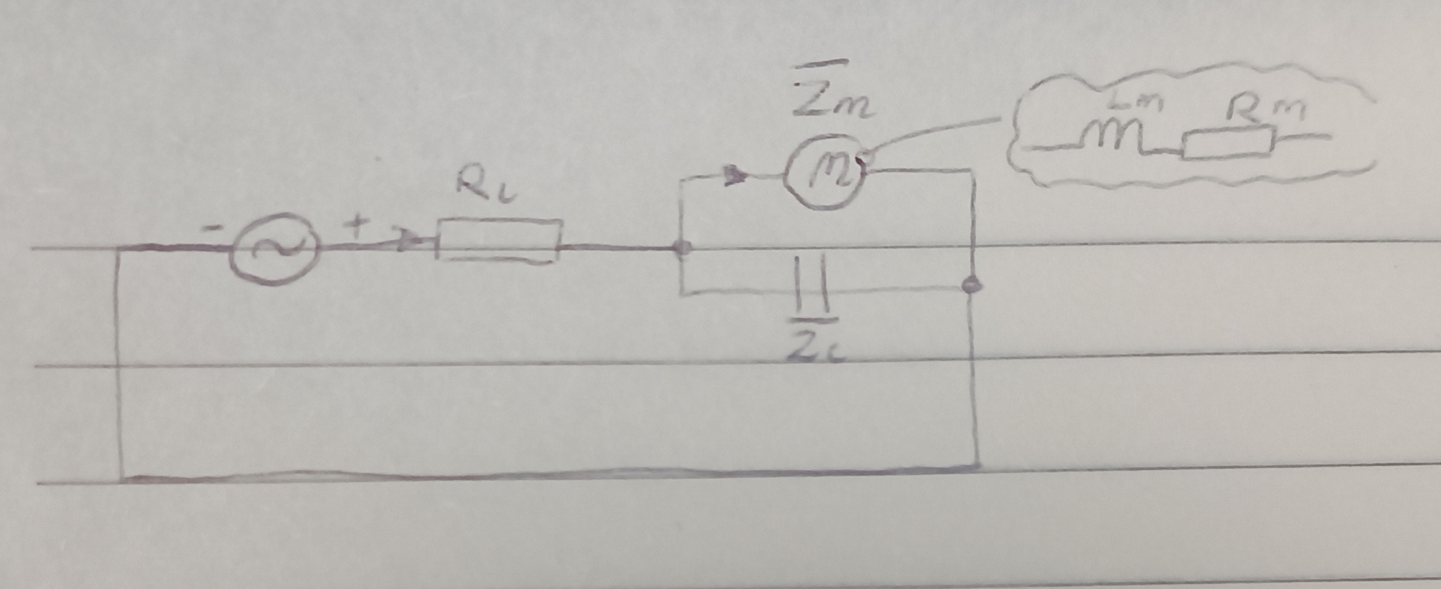
Take a real setup: a 240 V, 50 Hz supply feeds a line with resistance $$R_l = 6.67\ \Omega$$. At the end of the line, two branches sit in parallel: a motor (resistance $$R_m = 12\ \Omega$$, inductance $$L_m \approx 50.93\ \text{mH}$$) and a compensation capacitor ($$C \approx 127.32\ \mu F$$) wired in to fix the motor's poor power factor.
Step 1 — branch impedances. With $$\omega = 2\pi \cdot 50 = 100\pi\ \text{rad/s}$$: $$\underline{Z}_m = 12 + j(100\pi \cdot 0.16/\pi) = 12 + j16\ \Omega$$ $$\underline{Z}_C = -j\frac{1}{100\pi \cdot 400\cdot10^{-6}/\pi} = -j25\ \Omega$$
Step 2 — combine the parallel branches, the same way you'd combine parallel resistors, just with complex algebra: $$\underline{Z}_p = \frac{\underline{Z}_m \cdot \underline{Z}_C}{\underline{Z}_m + \underline{Z}_C} = \frac{(12+j16)(-j25)}{12-j9} = \frac{100}{3}\ \Omega$$ Then add the line in series: $$\underline{Z}_{tot} = \underline{Z}_l + \underline{Z}_p = \frac{20}{3} + \frac{100}{3} = 40\ \Omega$$. Notice this came out purely real — the capacitor's negative reactance exactly cancelled the motor's positive reactance. That's not a coincidence, it's the capacitor doing its job.
Step 3 — main current via complex Ohm's law: $$\underline{I} = \frac{\underline{U}}{\underline{Z}_{tot}} = \frac{240e^{j0^\circ}}{40} = 6\ \text{A}$$, in phase with the source voltage.
Step 4 — power. Complex power is $$\underline{S} = \underline{U} \cdot \underline{I}^*= 240 \cdot 6 = 1440\ \text{VA}$$, giving active power $$P = 1440\ \text{W}$$ and reactive power $$Q = 0\ \text{var}$$. Zero reactive power at the source is exactly what you want — it means the utility line only has to carry current that does actual work, not current that just sloshes back and forth between the coil and capacitor.
Exponential ↔ rectangular form, the part everyone forgets
Euler's formula is the bridge: $$re^{j\varphi} = r\cos\varphi + jr\sin\varphi = a + jb$$. Think of it as GPS directions vs. a grid: "walk 10 m at a bearing of -53.13°" (exponential form) is the same instruction as "6 steps east, 8 steps south" (rectangular form) — you're just choosing a different, equally valid way to describe the same vector. Concretely, $$10e^{-j53.13^\circ} = 10\cos(-53.13^\circ) + j \cdot 10\sin(-53.13^\circ) = 6 - j8$$.
Three-phase in one line
If a load is symmetric (identical on all three phases — the normal case for a three-phase motor), you never draw all three phases. You solve one phase as a single-phase equivalent circuit, then multiply the resulting power by 3. The two ways to wire a three-phase load:
Star (Y): each element sees the phase voltage $$U_f = U_L/\sqrt{3} \approx 230\ \text{V}$$ (for a 400 V line), line current equals phase current, draws 1/3 the power of the same load in delta.
Delta (Δ): each element sees the full line voltage $$U_L = 400\ \text{V}$$, line current is $$\sqrt{3}$$ times the phase current, draws 3× the power of the same load in star.
Star is used for motor start-up (lower inrush current) and for feeding single-phase household loads off the neutral; delta is used for continuous full-load running and for long-distance transmission (no neutral wire needed).
Worked example: a star-connected load fed through a long extension cable
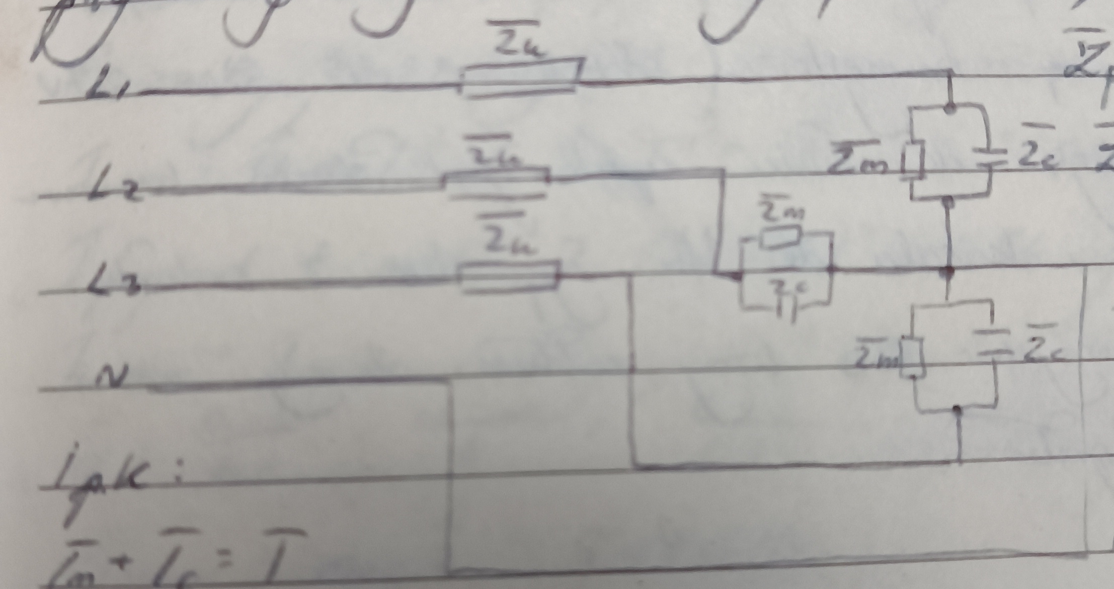
Take a three-phase circular saw with a star-connected (Y) motor, powered through a long workshop extension cable. Per phase, the cable itself has impedance $$\underline{Z}_k = 16 + j10\ \Omega$$, the motor winding has impedance $$\underline{Z}_m = 12 + j16\ \Omega$$, and a compensation capacitor built into the saw sits in parallel with the winding, with $$\underline{Z}_C = -j20\ \Omega$$. As before, we solve one phase as a single-phase equivalent circuit with phase voltage $$\underline{U}_f = 230e^{j0^\circ}\ \text{V}$$.
Step 1 — combine the parallel branches inside the saw (motor winding and capacitor), the product-over-sum rule again: $$\underline{Z}_p = \frac{\underline{Z}_m \cdot \underline{Z}_C}{\underline{Z}_m + \underline{Z}_C} = \frac{(12+j16)(-j20)}{12-j4} = 30-j10\ \Omega$$
Step 2 — add the cable impedance in series to get what the wall socket actually sees: $$\underline{Z}_{tot} = \underline{Z}_k + \underline{Z}_p = (16+j10)+(30-j10) = 46\ \Omega$$ The imaginary parts cancel exactly — the capacitor's negative reactance offsets both the motor's inductance and the cable's inductance, leaving a purely resistive total. That's not luck, it's the capacitor sized for exactly this job.
Step 3 — main current drawn from the socket, via complex Ohm's law: $$\underline{I} = \frac{\underline{U}_f}{\underline{Z}_{tot}} = \frac{230e^{j0^\circ}}{46} = 5\ \text{A}$$
Step 4 — voltage that actually reaches the saw. The cable itself eats some voltage, so the saw's terminals see less than the wall's 230 V: $$\underline{U}_p = \underline{I}\cdot\underline{Z}_p = 5\cdot(30-j10) = 150-j50\ \text{V} \approx 158.1\ \text{V}\angle{-18.43^\circ}$$ This is the number that matters if you're checking whether the motor is actually getting enough voltage to run properly at the end of a long cable run.
Step 5 — split the current between the motor and the capacitor, using the terminal voltage from step 4: $$\underline{I}_m = \frac{\underline{U}_p}{\underline{Z}_m} = \frac{150-j50}{12+j16} = 2.5-j7.5\ \text{A}, \qquad \underline{I}_C = \frac{\underline{U}_p}{\underline{Z}_C} = \frac{150-j50}{-j20} = 2.5+j7.5\ \text{A}$$ Adding these back together, $$\underline{I}_m + \underline{I}_C = 5+j0\ \text{A}$$, exactly matching the main current from step 3 — Kirchhoff's current law checks out, which is a good sanity check any time you split a current between parallel branches.
Step 6 — total three-phase power. One phase's complex power is $$\underline{S}_1 = \underline{U}_f\cdot\underline{I}^* = 230\cdot5 = 1150\ \text{VA}$$, purely real since current and voltage are in phase. For the whole three-phase machine, multiply by 3: $$P_{3f} = 3\cdot\text{Re}\{\underline{S}_1\} = 3\cdot1150 = 3450\ \text{W} = 3.45\ \text{kW}, \qquad Q_{3f} = 3\cdot\text{Im}\{\underline{S}_1\} = 0\ \text{var}$$ Zero reactive power at the wall means the compensation capacitor is doing exactly what it's there for — the socket only supplies current that does real mechanical work at the blade, none of it just sloshing back and forth in the cable.
That's the practical core of AC complex-number analysis: turn every component into a complex impedance, combine them exactly like resistors (series adds, parallel uses the product-over-sum rule), then read off current and power at the end. Everything else is bookkeeping. Thank you for reading! Next post: electromagnetic induction and where the Lorentz force actually comes from.
Read more