
categories: physics, automation & robotics, electrical engineering
Hello everyone, part two of the series. This one is about a chain of four cause-and-effect steps that shows up everywhere in robotics and automation: motors, generators, induction sensors, wireless charging, eddy-current brakes — all of it is the same four-step chain repeated with different geometry. Once you see the chain, the formulas stop being things you memorize and start being things you can derive on the spot.
The chain, in order
1) A changing current creates a changing magnetic field. 2) That changing field, passing through a loop, induces a voltage (EMF) in the loop. 3) If the loop is a closed circuit, that EMF drives a current through it. 4) That induced current, sitting inside a magnetic field, feels a mechanical force (or torque) that opposes whatever caused the change in the first place. Steps 1-2 are Faraday's law. Step 4's "opposes the change" part is Lenz's law. Step 4 itself is the Lorentz/Ampère force — this is literally how every electric motor and generator works.
Worked derivation: EMF induced in a loop near a straight wire
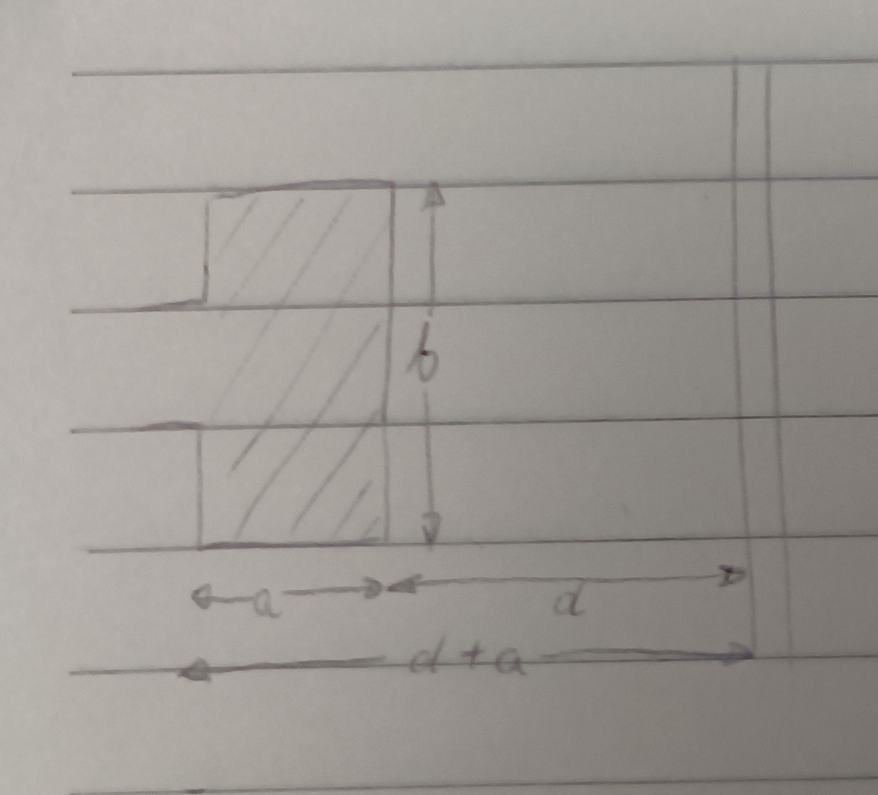
Setup: a long straight wire carries $$i(t) = I_0\sin(\omega t)$$. In the same plane sits a rectangular loop of size $$a \times b$$, with its near edge a distance $$d$$ from the wire.
Step 1 — field at distance r from the wire (Ampère's law for a straight conductor): $$B(r,t) = \frac{\mu_0 i(t)}{2\pi r}$$
Step 2 — integrate over the loop's area to get flux. This is the part everyone gets tripped up on: why do you integrate from $$d$$ to $$d+a$$, and not from 0? Because the field only counts where the loop physically is. Picture measuring a rug that starts 2 m from the wall and is 3 m wide — the rug covers the floor from 2 m to 5 m from the wall, not from 0 to 5 m. Same idea: the loop's near edge is at $$r=d$$, its far edge is at $$r=d+a$$, so those are your integration limits. Slice the loop into infinitesimally thin strips of height $$b$$ and width $$dr$$, parallel to the wire (so $$B$$ is constant across each strip), then sum: $$\Phi(t) = \int_d^{d+a} B(r,t)\, b\, dr = \frac{\mu_0 I_0 b \sin(\omega t)}{2\pi}\ln\!\left(\frac{d+a}{d}\right)$$
Step 3 — differentiate to get the induced EMF (Faraday's law, with the minus sign encoding Lenz's law — the induced voltage always opposes the change that created it): $$e(t) = -\frac{d\Phi(t)}{dt} = -\frac{\mu_0 I_0 b \omega}{2\pi}\ln\!\left(\frac{d+a}{d}\right)\cos(\omega t)$$ That's it — three steps, straight from Ampère's law to an induced voltage you could measure with a scope.
Where the mechanical force actually comes from
Steps 1-3 above only get you a voltage and, if the loop is closed, a current $$i_{ind}(t) = e(t)/R$$. That current is still just electricity — nothing is moving yet. The mechanical part is step 4: any current-carrying conductor sitting in a magnetic field feels a force, $$\vec{F} = i_{ind}(t) \cdot (\vec{L} \times \vec{B})$$ and if the loop is mounted on an axis, this becomes a torque $$M = i_{ind}(t) \cdot A \cdot B \cdot \sin\theta$$. This is the Lorentz force acting on the induced current, and by Lenz's law it always points in the direction that opposes the change that caused it — if the loop is free to move, it gets pushed/rotated to try to cancel the flux change through it. Every DC and induction motor is this effect, engineered on purpose; every "why does my hand-crank generator resist turning" is the same effect showing up as a nuisance.
One-line summary you can actually remember
Changing current → changing $$B$$-field → induced EMF in a nearby loop → induced current → Lorentz force on that current → force opposes the original change. Five arrows, and you can rebuild every formula above from them. Thank you for reading! Next post: transistor switching circuits and a first-order thermal model you can actually use to size a heatsink.
Read more